Introduction
I have been receiving satellite images for a little while now. Mostly with Automatic Picture Transmission (APT) signals but I want to go to the next level. High Resolution Picture Transmission (HRPT) signals seem like a good next step.
I found a couple of useful resources before getting started:
From the Beginner HRPT Guide I chose a design with dimensions:
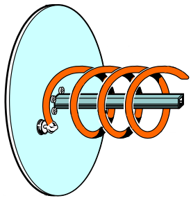
- 5.5 turns
- 56mm diameter
- 25mm turn spacing
- 130mm reflector diameter
- LHCP
There are STL files available to download so you can 3D print a nice wire guide; however, I don’t have a 3D printer.
The instructions for people who don’t seem a little sketchy: along the lines of “install a stick and jam plastic on it to help align the wire”.
It seems like it might be easier to find a cylinder to wrap the wire around with a printed 2d template.
Designing/building the antenna feed:
| Tools |
Supplies |
| 2D printer |
Old El Paso taco sauce bottle |
| paper cutters |
10 AWG Wire (2.5mm diameter) |
| drill |
2mm Aluminum plate (15x15cm) |
| carbide bits |
Male SMA connector |
| tin snips |
M2 nuts/bolts |
| soldering iron |
solder and flux |
| compass |
hot glue |
| hot glue gun |
|
| Inkscape |
|
Dish Assembly
| Tools |
Supplies |
| knife |
scraps of wood |
| wood saw |
double-sided tape |
| clamps |
wood glue |
Test Reception
| Tools |
Notes |
| SDR |
I used SMArTee |
| LNA/Filter |
I used SawBird GOES+ |
| male-male SMA cable |
keep it short (or use male-male adaptor instead) |
| usb extension cable |
|
| laptop |
running SatDump |
Designing the antenna feed
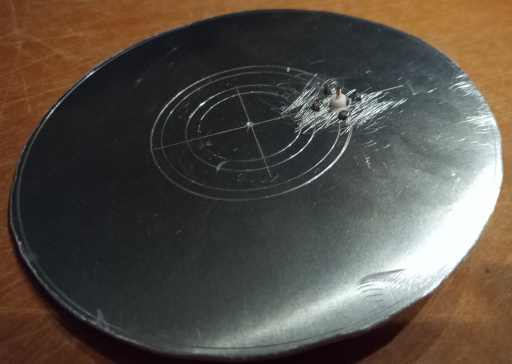
Make ground plane
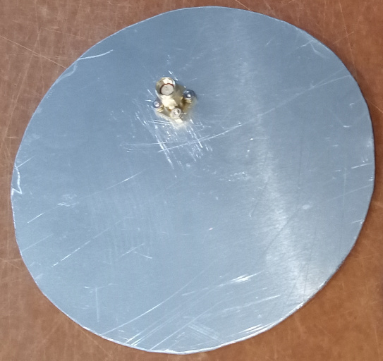
Simply ordered a 2mm aluminum plate at 15x15cm.
Found the centre and used a compass to mark 13cm diameter, as well as a radius of 2.7cm as a guide for the connector.
Used tin snips to cut the 13cm circle out.
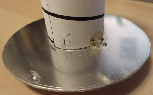
Add connector
I chose to use a male SMA connector as that provides a direct connection to my LNA.
Pick a spot on the 2.7cm radius circle and drill a hole large enough for the connector’s pin and insulator. I believe I used a 3/16ths cobalt drill bit.
Place the connector how you’d like it, and make markings in its mounting holes. Drill them out (I used a 3/32 bit), then use M2 hardware to secure the connector to the ground plane.
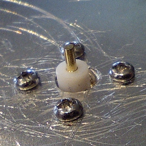
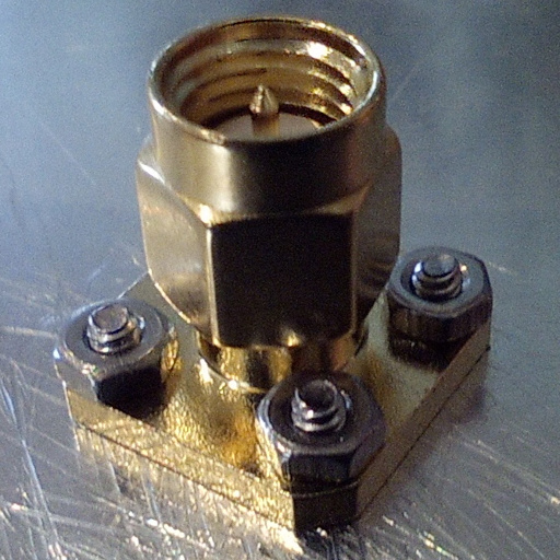
Note - if I were to do this project again, I’d rotate the connector by 45deg so the M2 hardware has a little more clearance from the bottle neck.
Choose wire
In terms of wire, the thickest solid copper wire I could find at the hardware store was 10AWG (2.5mm diameter) for $1.82/m.
It comes with a sheath that thickens it to roughly 3.8mm diameter.
Design 2D template
The diameter is supposed to align with the outermost edges of the wire, so the template we wrap around will be smaller by 2x the wire diameter.
With 2.5mm wire, we want a template diameter of 51mm. Which leads to a circumference of 160.22.
Now that we have the width of the template figured out, let’s figure out the height.
we have 5.5 turns with 25mm turn spacing, so the distance from the lowest wire centre to the highest is 137.5mm. Add the wire thickness (2.5mm) and spacing for the distance between the wire connector and the ground plane (2mm) and you get 142mm.
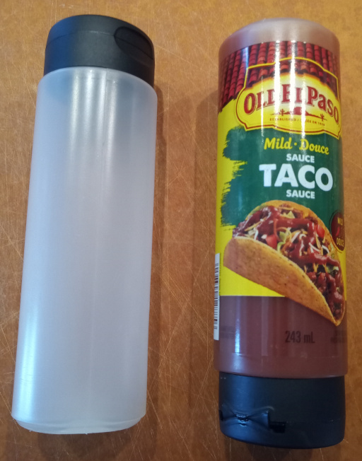
In my search, I found that a squeeze bottle of Old El Paso taco sauce was just about perfect.
The diameter averages 51mm and it’s height is more than enough.
You can even flip it and remove the cap so there’s clearance around the connector.
In the template, I made some alterations:
- Because of the variations in the taco sauce bottle, I pad the circumference by a couple of mm
- I have the wire starting a little above the base of the template because the connector is proud of the ground plane.
The template dimensions are now 163x142mm. I’ve created one in Inkscape:

Download the SVG Here
Building the Antenna feed
Prep the template:
- Print at 100% scale
- Verify the scale by measuring the 10cm line.
- cut out the dotted section at the bottom
- glue the 1cm tab on the right and wrap the template until the wire lines align
Mark the ground plate with some compass lines for help aligning the neck of the taco sauce bottle. I used radii of 14mm and 17.5mm for the inner and outer edges of the rim.
Then glue the bottle to the ground plate using the guides. You can see that if the connector were rotated 45deg, the glue is less likely to affect the M2 hardware.
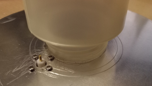
You should be able to slide the template over the bottle and align the cutout over the connector:
Next, remove the sheath from about 1m of the wire, wrap it to follow the template’s pattern, solder it to the connector and trim the end.
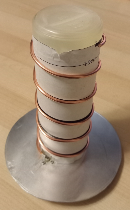
All that’s left is to remove the paper, and maybe add some hot glue at both ends of the copper helix to protect against mild bumps.
Some things I tried that seemed to work
- coil it tightly (without gaps in the wraps) around the sauce bottle and then pull the spring apart until it fits the helix length.
- remove the spiral from the tube and twist to tighten it a little more so it clamps around the bottle.
- wait to solder the wire to the connector until after the helix is in its final shape - bending the wire puts strain on the soldered joint.
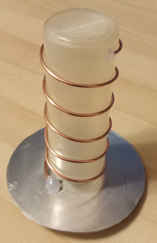
With the template and the taco sauce bottle, we have an easy way to create an HRPT antenna that checks off all the design requirements:
- 5.5 turns
- 56mm diameter
- 25mm turn spacing
- 130mm reflector diameter
- LHCP
Next up, mounting to a dish and testing!
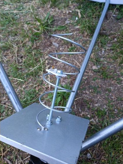
Mounting to dish
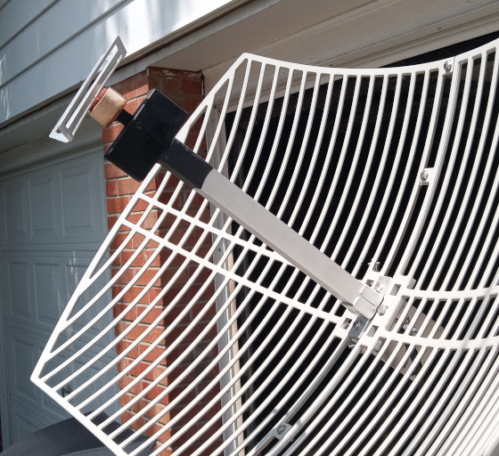
I was lucky to find a discarded tv satellite dish on the side of the road.
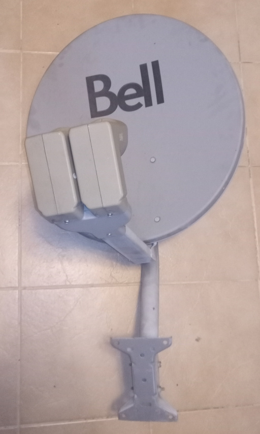
The beginner guide mentioned that the first twisting of the helix should be where the head of the existing TV feed head ends.
For this dish, it means that the arm needs to be extended or replaced.
Shoehorn in some scraps of garbage, glue some wood cut at 60deg.
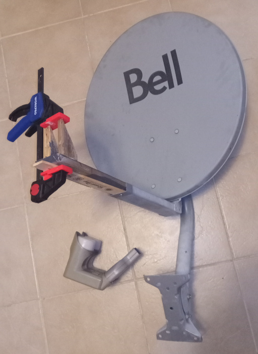
Double-sided tape the new antenna in place, and connect the lna/filter, then the sdr and a USB extension.
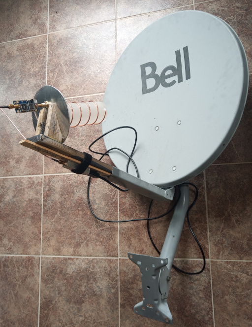
Tacotenna -> SawBird GOES+ -> SMA -> SDR
Testing
The first attempt bore no fruit. I was using SDR++ to record the baseband signal while watching the FFT waterfall to guide my aiming of the dish.
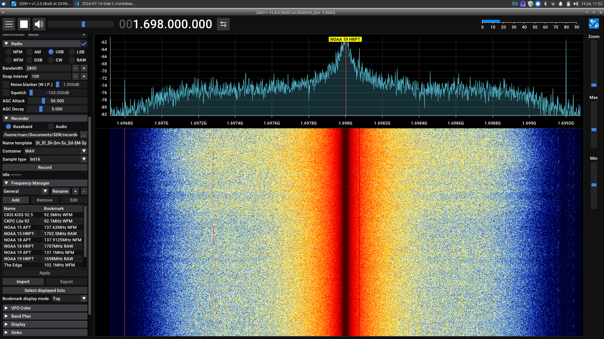
Settings used for SDR++ for NOAA 19 scan:
- set frequency for NOAA 19 HRPT to 1.698GHz
- set bandwidth (default 256KHz) to 2.56MHz
- enable RTL AGC (automatic gain control)
- record baseband, wav, int16
The waterfall wasn’t giving me any meaningful feedback, so I ended up waving the antenna around like a feather duster.
As expected, processing the output in SatDump gave nothing.
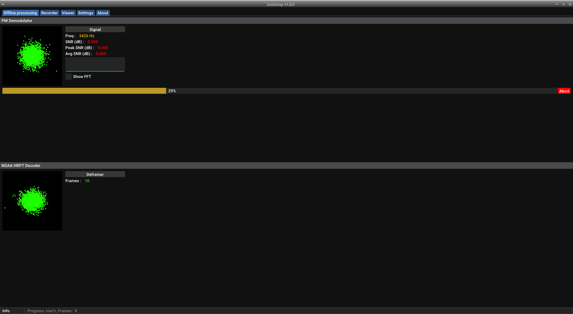
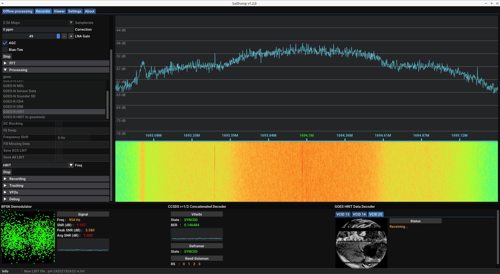
For my second attempt, I decided to try doing everything in SatDump. This proved to be very helpful to me.
Unfortunately, due to the commotion of success, I don’t have any screenshots of SatDump during the successful capture. But for NOAA 18 HRPT, I did the following:
- AGC on, but also max out other gain slider.
- Set freq to 1707MHz with sample rate of 2.56MHz
- no offset tuning or DC compensation.
- Start running the SDR
- then start the processing.
When it detects signal, it will automatically start converting to the image data. There’s still a way to record the baseband signal, but it is not required.
I was also happy to see that it saved all channel data in labelled folders and sub-folders for the specific scan attempt.
SatDump was easier to pinpoint the aim. Generally wave around until you get the 2d spectrogram to separate into circles, and then fine tune while watching the SNR.
My highest SNR was 8.14, but the high-average was about 6 and I spent a while around 1-3/
Seemed to start getting a second burst but only for a second. At the end of the track I had to do big rotations for the dish to pick up a signal.
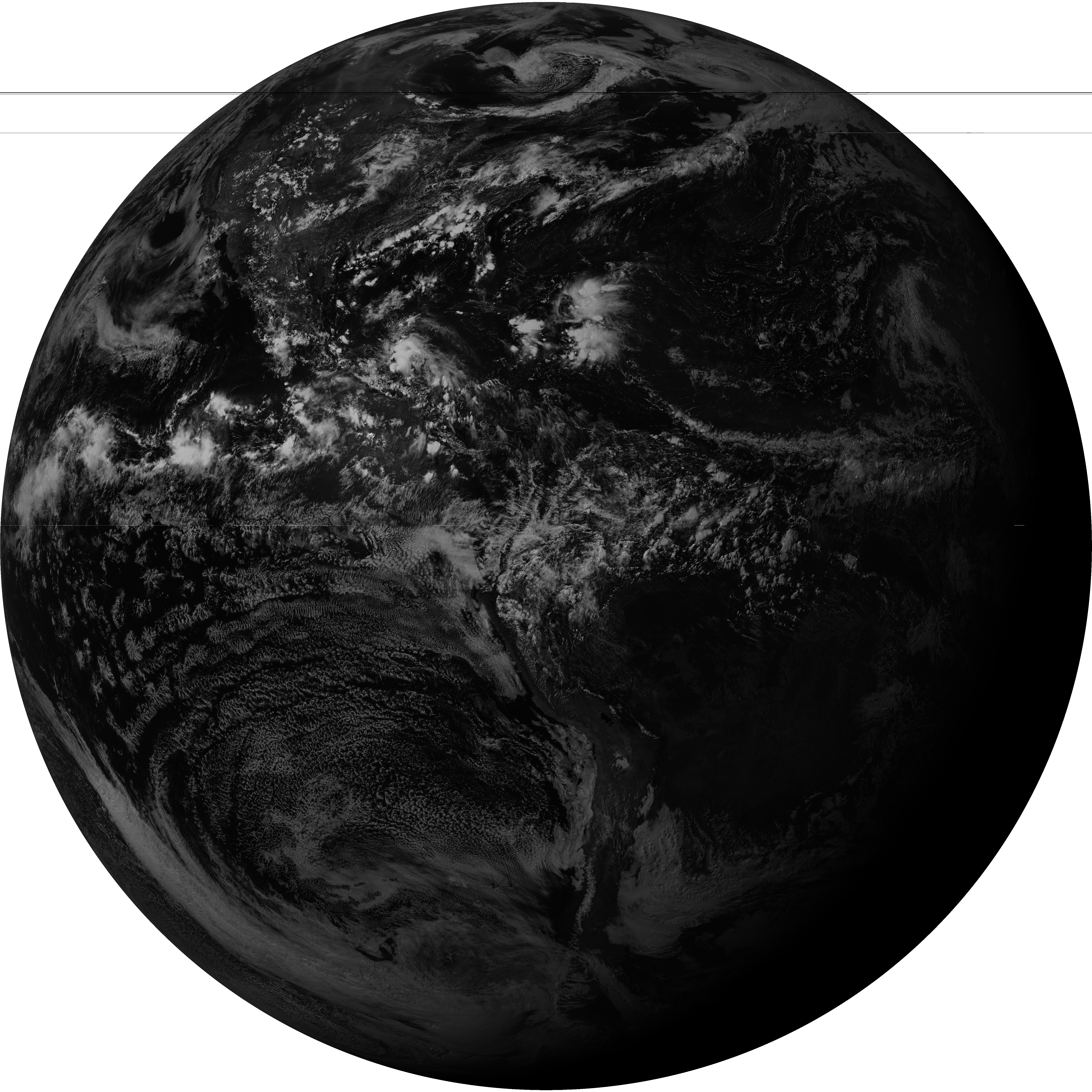
Results
It was the best type of a success: technically.
From the scan, SatDump produced a folder of images.
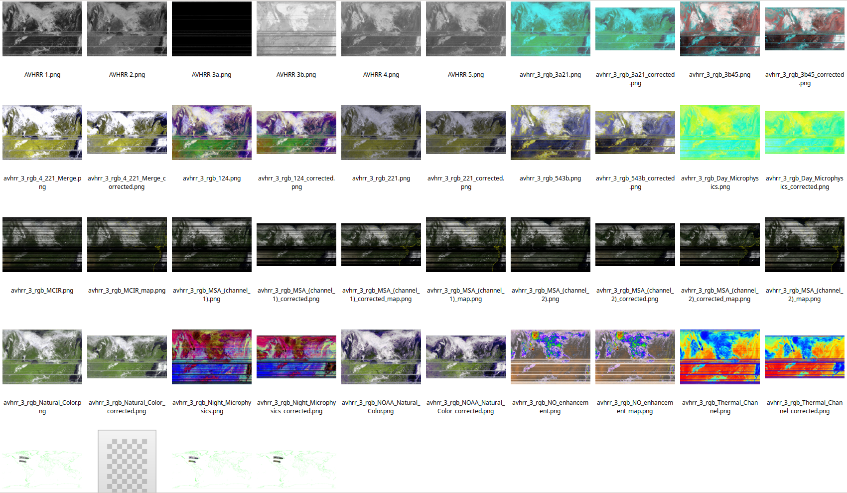
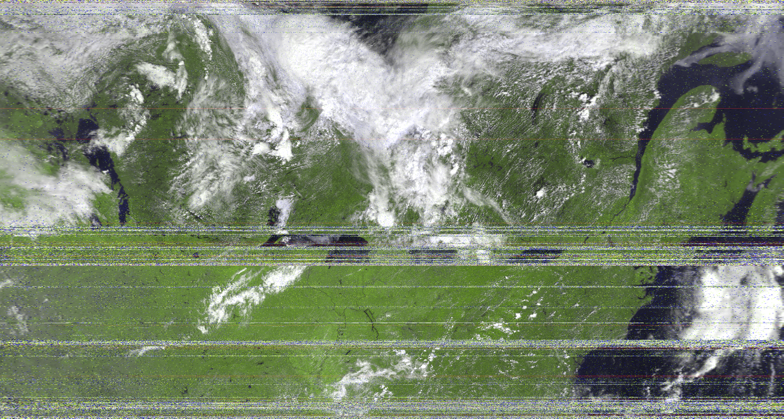
Here is one of the raw image channels that I was able to grab.

And another image after adding some colour and correcting for distortion.
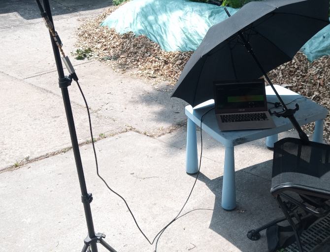
Lessons Learned and Next Steps
I’ll want to figure out a better way to position the dish; it’s a little cumbersome to hold the dish in one hand and the laptop in the others. Not to mention it must appear bonkers.
With my current SNR, it is difficult to fine-tune the dish orientation using the waterfall alone. Luckily, the demodulator in SatDump provides valuable visual feedback.
That said, I still had some issues tracking it by hand.
After having experience with the continuous APT signals being beamed, it was odd to deal with a signal that seemed to be transmitted in bursts. When the signal cut out, I would wave around to regain a non-existent signal

Replace the SMA cable between the LNA and SDR with a smaller connector. It is beneficial to minimize the distance between the antenna and the SDR.
Next up, HRIT signals from the geostationary GOES 16.
]]>

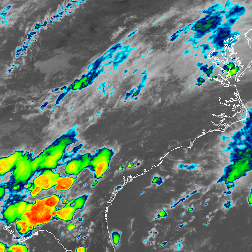
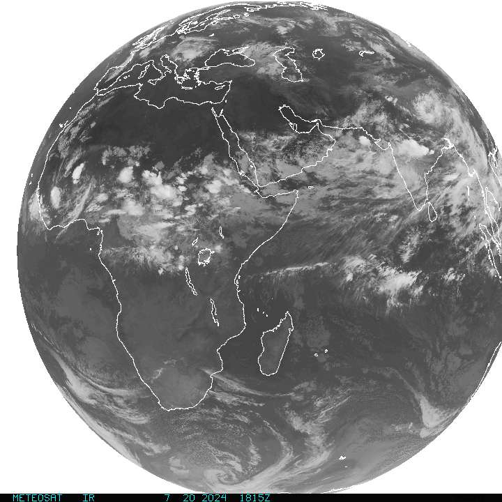
 If you look near the centre, you can see the reflection of the sun.
